Change Language :
drylin® T - system design, lateral, 1 rail and 2 trolleys or 2 rails and 4 trolleys
Step 2:
Check whether the distances between the applied forces are within the permissible values (see maximum permissible distances).
| Variant: 1 rail, 2 trolleys | Variant: 2 rail, 4 wagons | |
|---|---|---|
| sy + sz | < | 2 wx - Y0 |
| ay + az | < |
Step 3:
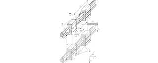
A = Coordinate origin
B = Fixed bearing
C = floating bearing
Calculating the required drive force
Firstly, two calculations must be carried out:


Variables in the calculations
| Fa: | drive force | [N] |
| Fs: | Mass force | [N] |
| Fy, Fz: | Bearing load in y or z direction | [N] |
| sx, sy, sz: | Distance of the inertial force in x, y or z direction | [mm] |
| ay, az: | Distance of the drive force in the y or z direction | [mm] |
| wx: | Distance between the wagons on a rail | [mm] |
| LX: | Size-dependent constant | [mm] |
| Zm: | Size-dependent constant | [mm] |
| Y0: | Size-dependent constant | [mm] |
| b: | Distance between the guide rails | [mm] |
| µ: | coefficient of friction, µ = 0 for static loads, µ = 0.2 for dynamic loads | |
| ZW: | Number of slides per rail |
Step 4:
Calculate the maximum bearing load


Variables in the calculations
| Fa: | drive force | [N] |
| Fs: | Mass force | [N] |
| Fy, Fz: | Bearing load in y or z direction | [N] |
| sx, sy, sz: | Distance of the inertial force in x, y or z direction | [mm] |
| ay, az: | Distance of the drive force in the y or z direction | [mm] |
| wx: | Distance between the wagons on a rail | [mm] |
| LX: | Size-dependent constant | [mm] |
| Zm: | Size-dependent constant | [mm] |
| Y0: | Size-dependent constant | [mm] |
| b: | Distance between the guide rails | [mm] |
| µ: | coefficient of friction, µ = 0 for static loads, µ = 0.2 for dynamic loads | |
| ZW: | Number of slides per rail |
The constant values
| Order number | LX [mm] | ZM [mm] | Y0 [mm] |
|---|---|---|---|
| TW-01-15 | 29 | 16 | 11.5 |
| TW-01-20 | 35 | 23 | 15.0 |
| TW-01-25 | 41 | 25 | 19.0 |
| TW-01-30 | 49 | 29 | 21.5 |
Coefficients:
| 1 rail, 2 carriages | 2 rail, 3-4 wagons | |
|---|---|---|
| K1 | |(ay+Y0)/Wx| | |(ay+Y0)/Wx| |
| K2 | (sy+Y0)/Wx | (sy+Y0)/Wx |
| K3 | |az/Wx| | |az/Wx| |
| K4 | |sx/Wx| | |sx/Wx| |
| K5 | |sz/Wx| | |sz/Wx| |
| K6 | |(sy+Y0)/Zm| | |(sy+Y0)/b| |
| K7 | |sz/Zm| | |(sz/b)-0.5| |
Step 5:
Check the maximum bearing load of the most heavily loaded bearing with the load calculated in step no. 4
Maximum permissible load
| Order number | Fymax, Fzmax [N] |
|---|---|
| TW-01-15 | 2,000 |
| TW-01-20 | 3700 |
| TW-01-25 | 5,000 |
| TW-01-30 | 7,000 |
Step 6:
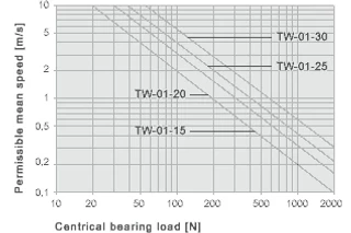
graph to determine the maximum permissible speed for the determined bearing load.
X = centric bearing load [N]
Y = permissible average speed [m/s]
Determination of the maximum permissible speed for the load from step no. 4
Contact us
Contact details

Seán Ryan086 0329555Submit form
Opening hours
Office hours
Monday to Friday from 8 am - 8 pm.
Live chat:
24h