Change Language :
drylin® W - Technical data
On this page you will find technical data such as dimensions for the carriages and rails, load capacity, as well as assembly instructions for this range. You will also find information on floating bearing systems, eccentric forces and general design tips.
Dimension information
| Type | Carriage length [mm] | Slide width [mm] | Coy [N] | Coz [N] | Mox [Nm] | Moy [Nm] | Moz [Nm] |
|---|---|---|---|---|---|---|---|
| WW-06-30-06 | 60 | 54 | 1680 | 840 | 25 | 34 | 34 |
| WW-06-30-08 | 80 | 54 | 1680 | 840 | 25 | 51 | 51 |
| WW-06-30-10 | 100 | 54 | 1680 | 840 | 25 | 68 | 68 |
| WW-10-40-10 | 100 | 73 | 4800 | 2400 | 96 | 170 | 170 |
| WW-10-40-15 | 150 | 73 | 4800 | 2400 | 96 | 290 | 290 |
| WW-10-40-20 | 200 | 73 | 4800 | 2400 | 96 | 410 | 410 |
| WW-10-80-10 | 100 | 107 | 4800 | 2400 | 178 | 170 | 170 |
| WW-10-80-15 | 150 | 107 | 4800 | 2400 | 178 | 290 | 290 |
| WW-10-80-20 | 200 | 107 | 4800 | 2400 | 178 | 410 | 410 |
| WW-16-60-10 | 100 | 104 | 8400 | 4200 | 240 | 270 | 270 |
| WW-16-60-15 | 150 | 104 | 8400 | 4200 | 240 | 480 | 480 |
| WW-16-60-20 | 200 | 104 | 8400 | 4200 | 240 | 690 | 690 |
| WW-20-80-15 | 150 | 134 | 12800 | 6400 | 525 | 670 | 670 |
| WW-20-80-20 | 200 | 134 | 12800 | 6400 | 525 | 990 | 990 |
| WW-20-80-25 | 250 | 134 | 12800 | 6400 | 525 | 1250 | 1250 |
The value for Coy also applies to Co(-y).
Table 01: Static load capacity for complete slides, each consisting of 4 housing bearings and plate


| Size 6 [mm] | Size 10 [mm] | Size 16 [mm] | Size 20 [mm] | |
|---|---|---|---|---|
| Single rail, round | • | • | • | |
| Single rail, square | • | • | • | • |
| Double rail, round | • | • | • | |
| Double rail, square | • | • | ||
| Complete system | • | • | • | • |
F x v graph, max. Permissible dynamic load (4 bearing system)

X = velocity v [m/s]
Y = load F [N]
A = size 6
B = size 10
C = size 16
D = size 20
E = size 25
diagram. 03: Fv-graph, max. Permissible dynamic load (4-bearing system)
Assembly instructions for drylin® W rail with complete slide: Housing bearings or with complete slide
During the installation process, a pressure force of at least 50 N on the centre of the mounting surface is recommended. Alternatively, a plastic hammer / soft-face mallet can be used to align the bearing during and after installation.
Tightening torque:
W-06: M4 = 1.5 Nm
W-10: M6 = 6.0 Nm
W-16: M8 = 15.0 Nm
W-20: M8 = 15.0 Nm


Floating bearings for guide systems
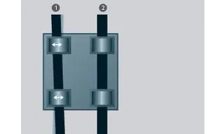
When using systems with two parallel guides, one side must be designed as a floating bearing. There is a suitable locating/non-locating bearing solution for every installation position, whether horizontal, vertical or lateral. This installation method prevents stiffness or jamming of the guide in the event of parallelism deviations between the guides. The floating bearing is realised by the controlled extension of the clearance in the direction of the anticipated parallelism error. This creates an additional degree of freedom on one side.
During installation, it is important to ensure that the floating bearing has approximately the same amount of clearance in both directions. The design of the fixed floating bearing system recommended by us can be seen in the illustrations below. The connection surfaces for the guides and carriages should have good evenness (e.g. milled surface) in order to avoid tension in the system. Minor unevenness in the connecting surfaces can be compensated to a certain extent by floating bearings.
Floating bearings aid assembly – when using single rails
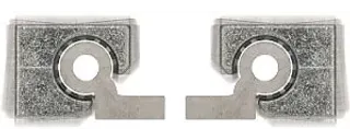
Users can reduce installation work with the drylin® W square profile. floating bearings, which can be selected in all directions (+/1 mm), compensate for misalignment and parallelism between the rails. Jamming, which can otherwise only be prevented by time-consuming parallel alignment of the system, can be ruled out.
Although drylin® W is a profile rail system, angle errors around the x-axis can be compensated. An angle of +/- 7° is available for this purpose. This effectively eliminates the distortions known from the assembly of sheet metal parts.


Eccentric forces
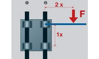
A few recommendations must be observed for the successful use of maintenance-free drylin® linear bearings**:** If the distance between the driving force and the fixed bearing is more than twice the bearing distance (2:1 rule), a static friction coefficient of 0.25 theoretically leads to jamming of the guidance.
The principle is not dependent on the load or the drive force. It is a product of friction and always relates to the locating bearing. The further away the drive is from the guide bearing, the greater the wear and the drive force required.
If the 2:1 rule is not observed when using linear plain bearings, the result is uneven movement or even blocking of the system. This can often be remedied with relatively simple modifications.
If you have any questions about the design and/or installation, please contact our application consultants.
Contact us
Contact details

Seán Ryan086 0329555Submit form
Opening hours
Office hours
Monday to Friday from 8 am - 8 pm.
Live chat:
24h